January 2005. Inspired by the webpages of Barloworld CVT technologies (check their patent info pages and their nice GIF animations), and challenged by Pete Peterson (the one who has improved my ratcheting CVT), I decided to find out if the modulation of the angular velocity by using universal joints can be demonstrated by a LEGO creation. Well it can.
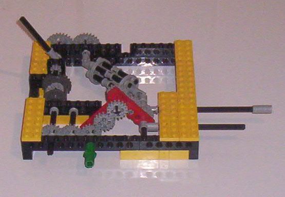
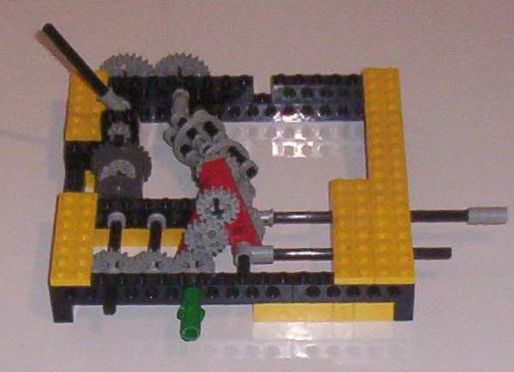
The following pictures will show how this can be done. The green handle is the input velocity axis. If this handle is rotated , the pointer like beam at he left side will swing a few degrees like a pendulum. The maximum full swing angle (about 45 degrees) depends on the angle of the two universal joints. This angle can be varied by pulling or pushing the bar at the rightside. The differential subtracts the angular velocities of the input axis and the output of the universal joints. If the angles of the joints are minimal, the bar is fully pushed into the device, the modulation is minimal and the pointer hardly moves. If the bar is fully pulled out the modulation is maximal and the pointer swings about 45 degrees.
For the construction of a CVT , a device is needed to extract a rotation from the pendulum motion. Further, one or two of these devices should run simultaneously in different phases, in order to take more advantage of a full rotating cycle of the input.
Unfortunately, in this design appears to be so much gear lash that you can block manually the pendulum motion without causing harming frictions in the rest of this device. So, extraction of the top cycle pendulum speed by means of a clutching device, or any other device, will not work for this design :-(
February 2005. Pete Peterson has beat me again! He send me
a number of pictures and gave me permission to show them on the web.
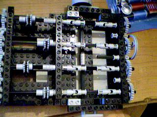
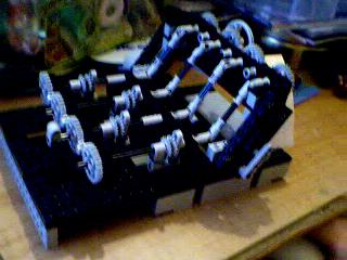
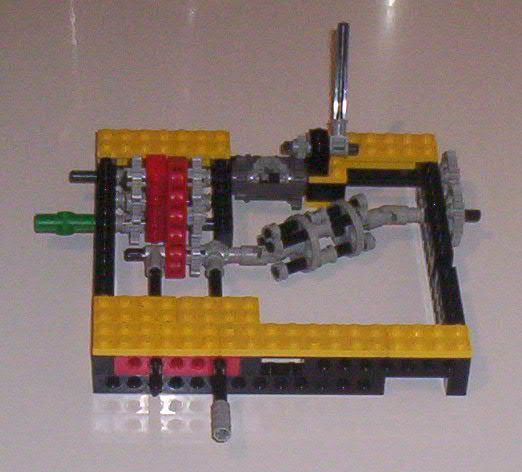
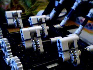
The input is the wheel at the right side of the structure. The input rotation is distributed to four pairs of universal joints and ratchets. The joints are connected in such a way that their output angular speeds are maximal (or minimal) in different quarters of a full rotation cycle. The ratchets, shown in more detail in the next two pictures, transmit torque when the the input angular speed is higher than the output speed. Since the four outputs of the ratchets are coupled, only one of them can transmit torque depending on the phase of the input rotation. By changing the angel of the universal joints, the strength of the modulation of the input angular velocity is changed. The output velocity can be varied between 1 and 1.3 The ratchets appeared to be the critical parts in this design. Pete succeeded very well in designing a very small ratchet that might have many more applications
February 9th. Check this out! It varies from 1:1 to about
1.3:1, but not enough force for anything useful. But it works! The ratchets
are where it needs improvement, they have only 28 precision..... We need something
like the 48 but not so big!
The distributors are the key, one is needed on both sides. The input is as the
'top' of the shifting section, the ratchets at the anchored end. I managed to
get 28 precision from the 14t gears, because they offset when places correctly,
and the ratcheting piece oscillates via play from one side to another. Works,
but not well enough :-) I can ldraw the ratchet for you, if you'd like. It's
very nice :-D The wheel you might see on the far end controls the shifting,
it's on an axis to the parelell lifting section, the other axis is to be used
by the drivepiece to run power from an 'anchored' motor to the far end of the
shifting section
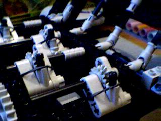
Use rubber band with least force possible, just enough to
lock it ideal. Also, use only new "green" ratchet as pictured, older
ones will not work due to unsmooth surface along ratcheting surface.
Red I use for input, blue for output. I dont know why, it works either way.
Rubber band goes around the piece, over and under between the gear and green
ratchet. Has very good action, the type of gear allows for easy ratcheting action,
combined with the green it makes a very good ratchet overall. 14 resolution,
as in 14 positions in 360* with which to ratchet,
On the second ratchet, allow 1/16 play around the green. Same as other. Might
want to use more rubber band force. 28 resolution. Notice how when ratcheting,
it jostles back and forth with its play. Ideal!
February 11th. fixed it!! Works much better, with a good ratio. But it's extremal,
only works in .07ish ratios, from 1:1 to 1:3. But it definitly works! I redid
the ratchets, they are less precise but have less friction. This is another
key... Too much friction here locks the whole deal up. I have it running on
a worm so it's slow. But it works so well!! I'll send more pics tomorrow. I
know I can make one smaller, it'll take time :-) I'd love for you to publish!
I have my own webpage, but it's mostly my airplanes ;-) It's get more attention
there, anyhew. I'll work on it saturday night, got nothing else to do.
In summary:
Less ratchet friction=better
More ratchet resolution=better
Slower overall speed=better
You can download here his Ldraw designs version 1 and version 2.
Ideas and comments are welcome!
![]()