 I stronly recommend to study the pages
on that device firstly. After a lot of puzzling with differentials I could
finally produce the demonstrator that is shown in the next picture..
I stronly recommend to study the pages
on that device firstly. After a lot of puzzling with differentials I could
finally produce the demonstrator that is shown in the next picture..
January 2, 2008. Because it is not easy to
built a fully functional helicopter rotor with swash plates with LEGO parts,
I decided to try another approach. The idea was to extend my old idea for using
differentials for the collective pitch control to the collective control as
well. This old idea was demonstrated with a balance and it worked very wel.
I stronly recommend to study the pages
on that device firstly. After a lot of puzzling with differentials I could
finally produce the demonstrator that is shown in the next picture..
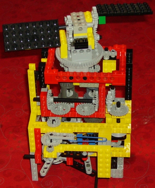
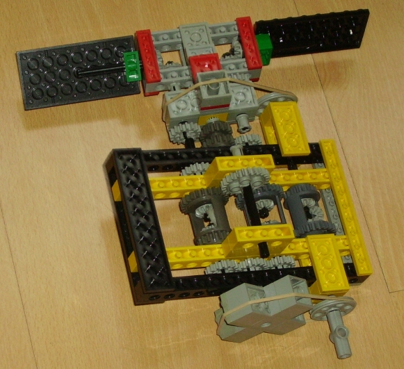
This picture needs a lot of explanation that is given in the sections on the rotor head, the adder/subtractor for realizing a 1:7 gear ratio, the collective control and and the cyclic control.
The rotor head. The construction consists of a rotor head with two blades. The pitch of the blades are controlled separately by two different axes. The difference in rotation speed between the outer ring and the central axis controls the pitch of the blade axis in the upper part of the picture. The difference in rotation speed between the outer ring and the differential (no crown gears inside) controls the pith of the blade axis in the lower part of the picture. If the rotation speeds of the outer ring, the central axis and the differential are equal , the pitch of the blades will not change.
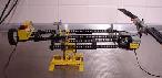
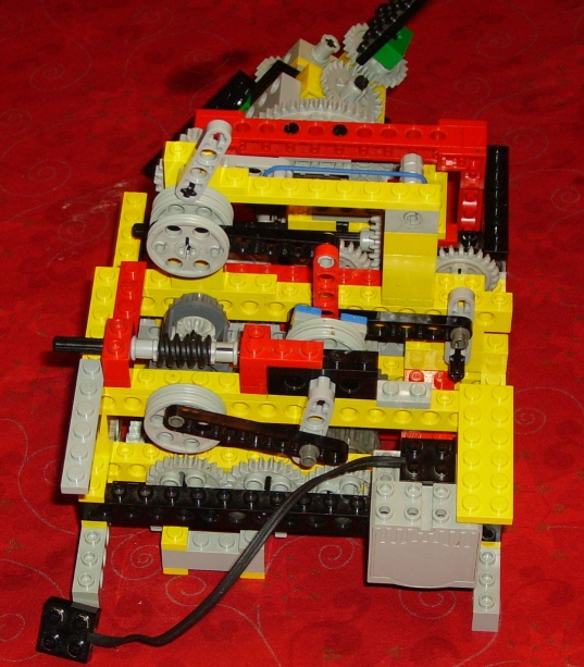
The adder/subtractor for realizing a 1:7 gear ratio.The next picture shows another view of the demonstrator and a close up view on the gear train that drives the outer ring of the rotor head..
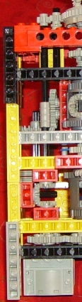
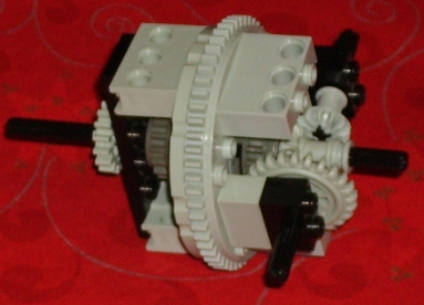
The motor at the bottom left corner drives all the rotor mechanisms. This motor drives the outer ring of the rotor head with a snall 8 tooth gear. The outer ring has 56 tooth, so the gear ratio is 1:7. In order to get the same rotatoin speed for the axes that control the pitches of the blade, I would need a second ring. Unfortunately, I didn't have a second one, and I have found a way to produce the 1:7 ratio with the help of a adder/subtractor. The next picture shows the adder subtracter in a close up view . The gear ratio's from the horizontal axis in the bottom with the 8 tooth gears to the 24 tooth crown gears that connect with the differentials are 1:4 and 1:3 . The result is that the gear ratio between the 3 horizontal 24 tooth gears at the bottom and the 4 24 tooth geara at the top is 1:7. The rotation speed of the 24 tooth gears is 7 times slowed down. The output of the adder subractor is used for driving the axes that control the pitch of the blades.
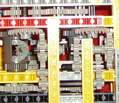
The collective control. This controls the average pitch of both blades. For crating this control, I had not enough differntials in my possession. This differntial should have been positioned between the motor and the axis that drives the rotor head. The close up view shows a three small crown gears between three red 2x1 technic bricks.This is where the differential should have been positioned. The average pitch can be contrlled by rotation of the differential. It causes a phase shift between the rottaion of the rotor head and the two axes that control the pitch of the blades
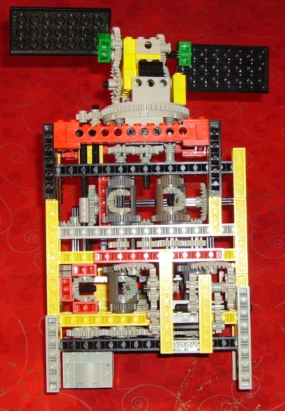
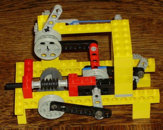
The cyclic control. This controls the alternating change of the pitch of the blades during one rotation cycle of the rotor head. Therefore we need a mechanism that produces an alternating rotation of a view degrees, and control mechanisms for the amplitude and the phase shift for this alternating rotation. The next 2 pictures give other views on the demonstrator that show more details of these mechanisms. The output of the adder-subtractor (not visible in both pictures) is connected to the input axis of the differential. The output of the differential is visible and is connected to the black lever and the grey crank that makes the wheel in the middel oscillate. The phase shift is controlled with the worm wheel. This alternating movement is transferred to a 24 tooth crown gear with a second lever and crank. The amplitude of the oscillating rotaion of this gear is controlled with the handle in the top and the red lever. The amplitude is zero when this handle is in the neutral position. The handle always returns to the neutral position with the help of the blue rubber string.
The output of this mechanism is connected with a number of crown gears to a set of differentials that are visible under the red technic beams. The input of these differentials ar connected to the output of the adder-subtractor and the outputs are conected to the axes that control the pitch of the blades.
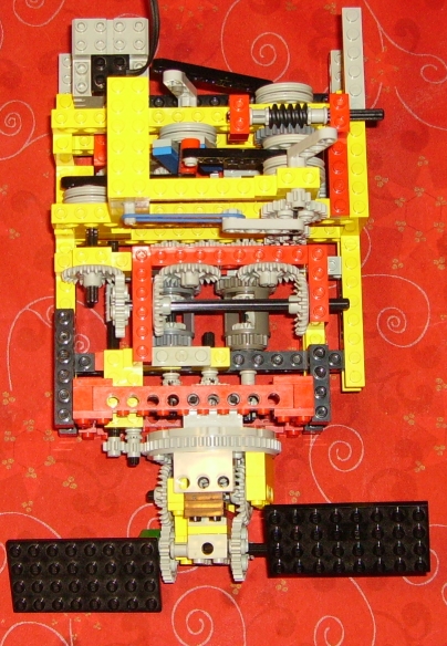
The demonstrator works, but I am still not happy with the result. Each blade can be moved manually ina range of almost 90 degrees due to the relatively large number of gears in the two differntials of the cyclic control. As a result, the efeect of cyclic control can only be seen with large amplitudes. The rotation speed of the rotor head is very low. The demonstrator can not work as a directionale fan as proposed by Leo Dorst. Nontheless, I am proud that I have solved this puzzle: how to built a LEGO rotor without a swash plate. I wonder if this concept has ever been tested with real helicopters.
Januari 19, 2008. I have strated to work on a new design that can work without th LEGO turntable. The following pictures show how far I hav got so far.
This structure has to be combined somehow with this:
![]()