LEGO 1:13 6x6 Truck Trial 2009
Part 1: the introduction of the new LEGO Power Function motors .
May 2009, There were two reasons for me to start again with experiments to get the perfect trial truck. The introduction of the new Lego power function motors and the 2009 LOWLUG meeting in Gendringen where a very nice trial truck circuit was introduced. A lot of pictures can be found on: http://www.brickshelf.com/cgi-bin/gallery.cgi?f=377099 . I hope to be ready for the next meeting!
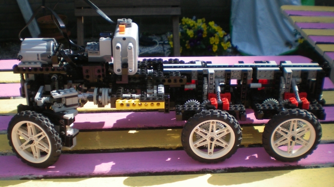
This page describes the first results obtained with a 6x6 chassis, a XL PF motor for driving, a small PF motor for steering and IR remote control. The batteries have to be carried now by the truck , but the new motors can produce more than sufficient power. The big question now is: can we keep the gears intact?
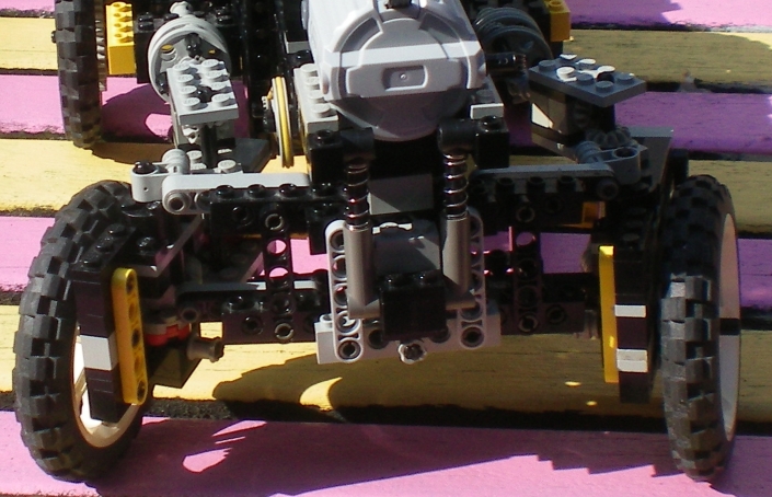
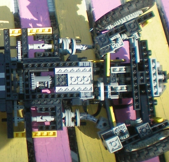
The next 2 pictures show the positoin of the PF motors for driving and steering. The IR receiver for remote control and the battery holder have been provisionally attached. The XL PF motor at the front drives directly the differntial in the middle using two flexible joints and a 1:3 gear ratio speed reduction. The use of the flexible joints result in a slightly noticible modulation of the speed. Therefore , it is recomended to avoid the use of relative large angles for these joints. The small PF motor is attached to the chassis and drives the steering mechanism with a belt. This steering mechanism works with a wormwheel and a 24 tooth gear, and is part of the front wheel suspension thatcan move up and down
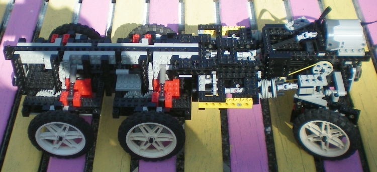
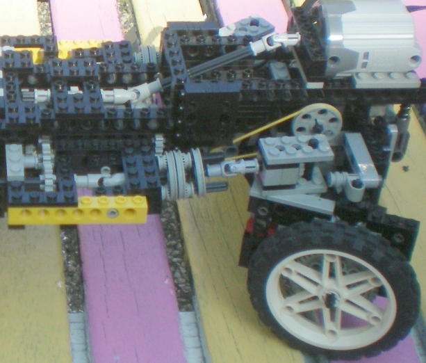
The next three pictures show the back wheelsuspension. The back wheel suspension works more or less like the suspension of a Tatra. The difference is that the central driving axes for the right and left wheels are not colinear but separated. The wheel axes are not colinear , just like in a Tatra.. There is no reduction, except at the wheels (1:5). The swing arms for every wheel are longer than in a Tatra, resulting in smaller angels when the wheels go up . This appeared to be possible by using the left acentral axis to drive the right wheels and the right central axis to drive the left wheels.
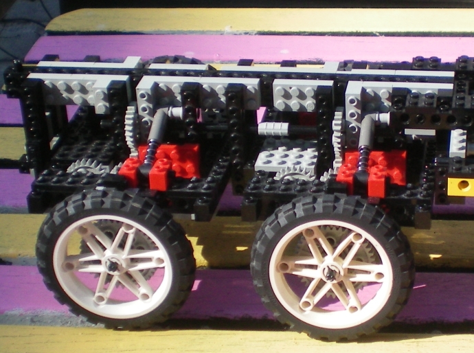
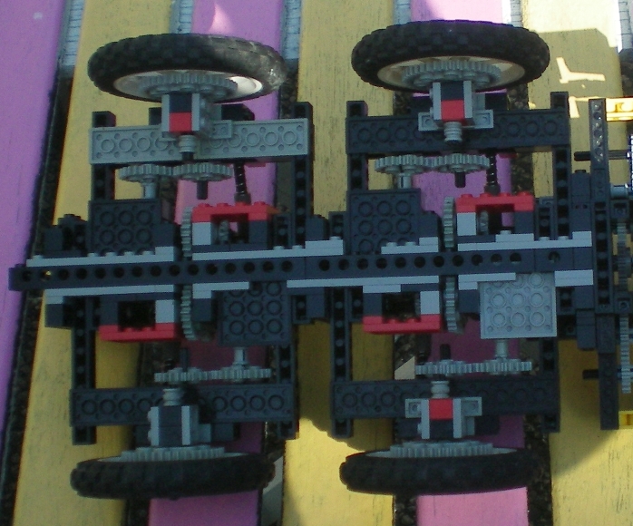
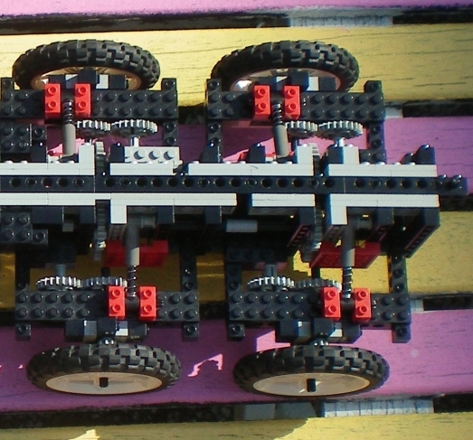
The next 3 pictures show the front wheel suspension. The front wheels suspension can move up and down by rotating around an axis above and just behind the steering motor. By using the freely rotating 24 tooth gears it was possible to make two gear trains that connect the left central axis (that drives the right back wheels) to the right front wheel , and likewise connect the right central axis to the left front wheel. The steering beams are connected to an arm and behave like a steering mechanism with an Akkerman correction.
This car appeared to drive so well, that I got tempted to make a gear box for higher velocities. Therefore, I did some experiments with less gear reduction to the central differential. This resulted in broken gears inside the differential and broken 24 tooth gears in the gear trains. I conclude from this experiment that I can only get higher velocities by reducing the gear ratio's at the wheels. However, this will be such a big change that I will have to rebuild the car. The front wheel suspensoin appeared to be very strong and effective. However, its design results in a slight instability. The front of the car can make small movements left and right wards by allowing for slight tilting of the front wheels. Therefore a classical stiff suspension that rotates around one central axis might be better. Now, the next question to answer is: what kind of a truck can be built on this chassis?.